filmov
tv
The circuit diagram shown here corresponds to the logic gate
0:02:23
The circuit diagram shown here corresponds to the logic gate
0:11:03
The circuit diagram shown here corresponding to the logic gate
0:07:07
, , The circuit diagram shown here corresponds to the logic gate, - (1) NOR (2) AND - (3) OR,
0:01:40
The correct Boolean operation represented by the circuit diagram drawn is :
0:01:46
The correct Boolean operation represented by the circuit diagram dr...
0:03:36
The correct boolean operation represented by the circuit diagram drawn is [NEET 2019] (a) NOR (b)...
0:05:42
Logic Circuit Analysis using Truth Tables
0:08:03
Digital Logic - implementing a logic circuit from a Boolean expression.
0:22:10
Diode Logic Gates - OR, NOR, AND, & NAND
0:01:30
How to Find the Boolean Expression from a Circuit Diagram
0:54:07
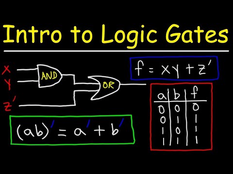
Logic Gates, Truth Tables, Boolean Algebra AND, OR, NOT, NAND & NOR
0:13:02
Making logic gates from transistors
0:06:22
Find Boolean Equation and Truth Table from Logic Diagram
0:09:25
Logic Gates and the Ripple Carry Adder
0:29:44
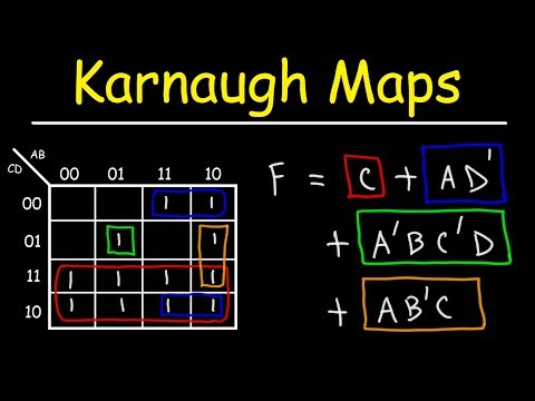
Introduction to Karnaugh Maps - Combinational Logic Circuits, Functions, & Truth Tables
0:02:44
Logic gates | Previous year physics problem | Semiconductor | Raja sir
0:15:15
Making Optical Logic Gates using Interference
0:01:58
Writing a Logic Expression From a Truth Table: 3 Inputs
0:06:02
Logical Gates ( Drawing a Circuit that Corresponds to a Boolean Expression ) - Part 4
0:13:44
Single qubit and its logic gates
0:08:12
Draw the logic diagram that corresponds to the VHDL description of a combinational circuit
0:15:45
Boolean Algebra & Redstone Logic Gates - LRR #3
0:02:14
How to Find the Boolean Expression for a Circuit Given the Input/Output Table
0:18:24
Carry Look Ahead Adder (CLA) Explained
Вперёд
join shbcf.ru
 0:02:23
 0:11:03
 0:07:07
 0:01:40
 0:01:46
 0:03:36
 0:05:42
 0:08:03
 0:22:10
 0:01:30
 0:54:07
 0:13:02
 0:06:22
 0:09:25
 0:29:44
 0:02:44
 0:15:15
 0:01:58
 0:06:02
 0:13:44
 0:08:12
 0:15:45
 0:02:14
 0:18:24